KRAK LLC
Arduino Modbus connection to a C-more HMI | January 4, 2013
Using an Arduino to collect information from an array of sensors is an economical alternative to using a PLC when the data collection is not critical. In this post I will explain the basics of connecting the hardware of an Arduino to a C-More touch panel from Automation direct. I will then show a basic setting to allow MODBUS communication to work between the two devices.
Hardware you will need:
C-more touch screen: http://www.automationdirect.com/adc/Shopping/Catalog/Operator_Interfaces/C-more_Touch_Panels/C-more_Touch_Panels_(all_sizes)/EA7-S6M-R
C-more Comm cable: http://www.automationdirect.com/adc/Shopping/Catalog/Operator_Interfaces/C-more_Touch_Panels/C-more_Touch_Panel_Programming_Software_-a-_Cables/EA-2CBL
Arduino, in this case I used a Duemilanove:
http://www.nkcelectronics.com/arduino-duemilanove.html
RS232 to TTL converter:
http://www.nkcelectronics.com/RS232-to-TTL-converter-board-DTE-with-Male-DB9-33V-to-5V_p_369.html
Parts to make a rj12 to db9 connection. I actually used a serial cable cut in half and spliced into a RJ45 jack. You may want to consider a part like this:
http://www.buy.com/retail/product.asp?sku=229955393&listingid=209691315
Software you will need:
C-more programming software:
The Arduino IDE, I used version 1.01. At the time of writing this 1.03 is available.
http://code.google.com/p/arduino/downloads/list
The MODBUS library that I got to work with the C-more.
http://code.google.com/p/arduino-modbus-slave/downloads/detail?name=MODBUS.zip&can=2&q=
*note this library does not work with Arduino IDE prior to the 1.00 release.
Setting up the hardware.
Create the connector to convert the db9 connection to the RJ12 connection.
http://media.nkcelectronics.com/downloads/rs232ttl_DTE_v1.1.pdf
DB9 connections required are pin 2, 3,and 5. Pin 7 and 8 will not be used.
To make the RJ45 jack as I did connect make these connections.
DB9 — RJ45
Pin 2 – B4
Pin 3 – B5
Pin 5 – B2
When plugging in the RJ12 to the RJ45, be sure to center the plug in the jack.
###Edit adding Photo to show the intermediary cable.

- DB9 to RJ45 hacked cable. Ideally should be DB9 to RJ12.
-
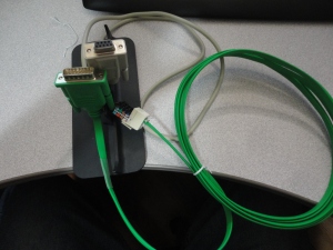
Here the EA-2CBL RJ12 plug is plugged into the center of the RJ45 jack.


( of course you can create your own DB9 to DB15 cable instead )

http://www.automationdirect.com/static/specs/cmorecables.pdf
DB9 |–| DB15
Pin 2 – Pin 3
Pin 3 – Pin 2
Pin 5 – Pin 5
Connecting the Arduino with the RS232 to TTL DTE board
Place jumpers on the RTS and CTS connections at the top of the board. 
Then make these following connections:
Arduino |—| DTE
5V – VCC
Gnd – GND
Digital pin 0 – RX (Use a jumper wire or place a switch in the middle of this connection.)
Digital pin 1 – TX
Do not connect the RTS or CTS pins from the board to anything.
Configure the Software.
For the Arduino:
Place the MOBUS library into the Arduino IDE library. See this for more information on how to do that: http://arduino.cc/en/Guide/Libraries
You can also copy the MODBUSslave example into the example folder.
Launch the Arduino IDE.
Open the MODBUSslave example. ( from the example menu or by navigating to it in the MODBUS library folder.
Now connect to your board. Remove the jumper to the RX pin. ( or turn off the switch if you used one) This will allow the computer to communicate with the Arduino. If you forget to do this, the DTE board will interfere with the upload of the sketch.
Upload the Example to the board.
Once complete, reconnect RX to D0.
C-more setup.
In the C-more software, Start a new project for the panel you have.
Go to Setup -> Panel Manager
On the com port, select the DEV001. Now would be a good time to rename this to ARDUINO.
Set PLC Protocol to Modicon Modbus RTU
Select direct connection
Set PLC SLAVE number to 1.
Baud Rate 9600
Parity None
Stop bit 1
Control RTS No
Require CTS No
Select RS 485 No
Byte Order High Byte, Low Byte
Word Order Low Word, High Word
Character Order in register Char1, Char2
Registers per Message 32
Coils per message 64
Register Write Function Code 06
Coil Write Function Code 05
Time out 30
Poll time 3
Click ok.
Let’s place a Numeric Display on the screen,
In the Data Display tag open the tag database to create a new tag.
Click on Add

Select ARDUINO for the device name, Give the tag a name like ReadOnlyRandom.
Set it to Unsigned INT 16
Select memory type 3
Enter an address of 1
Click ADD, Select the new tag Click OK. (notice that the PLC address is shown as 30001)
Click OK again to assign the tag to the display.
Save and send the project to the C-more.
Test it!
Connect the C-more to the Arduino using the com cable.
You should see LEDs on the DTE board flicker and a random number updating on the C-more screen. Congratulations, you have gotten past the biggest hurdle to getting a C-more to talk to an Arduino.
If you do not see this, check that you have RX and Digital pin 0 connected. Also try swapping the RX and TX connections.
Writing to an Arduino
Ok so now you can read from an Arduino, but how about writing to it.
Continuing with the example, let’s add a Numeric Entry in the same fashion as we did with the Numeric Display.
But this time when you add the new tag, Name it WriteableNumber with a memory type of 4 and an address of 9.

Save and transfer the project to the screen.
You should now see a 9 in the new entry.
Change the 9 to a different number. Now you have written to the Arduino.
To make use the register in the Arduino, update the example to use regBank.get(40009).
So in this post I covered how to setup the hardware to between a C-more touch screen HMI, and an Arduino. I also showed how to load the MODBUS library and example onto the Arduino. Lastly I showed how to configure the settings on the C-more to make use of the MODBUS RTU protocol in conjunction with the supported features of the Arduino.
The MODBUS library I used is not the only one available on the web, but it is the first one I got to work with a C-more.
Remember, when you are uploading to the Arduino, you must remove the RX connection.
In the next post, I will share a derived library that takes advantage of SoftSerial. This will allow You to connect the DTE board to Pins 2 and 3 instead of 0 and 1. There by allowing you to upload to the Arduino while remaining connected to the C-more.
Lastly I will share some methods to make it easy to read and write discrete bits using whole registers, instead of coils.
Please let me know what you think of this post. I welcome questions and feedback.
Resources:
http://code.google.com/p/arduino-modbus-slave/downloads/detail?name=MODBUS.zip&can=2&q=
http://www.nkcelectronics.com/RS232-to-TTL-converter-board-DTE-with-Male-DB9-33V-to-5V_p_369.html
http://en.wikipedia.org/wiki/Modbus
http://www.automationdirect.com/static/specs/cmorecables.pdf
http://media.nkcelectronics.com/downloads/rs232ttl_DTE_v1.1.pdf
http://forum.automationdirect.com
34 Comments »

Thanks so much for your tutorial. I have several PLC’s
including a DL260, DL05 and a Click along with a
CmoreMicro touch screen panel. I have often thought using the touch screen and PLC along with interfacing to a micro could be useful. I do have an Aruino UNO and also a wide assortment of Atmel chips. I have been using the ICCAVR C compiler but wanted to use a Linux (Ubuntu) to develope with the Atmel. So far, unable to get AVR-GCC, CodeBlocks working. But at least I can use the Arduino IDE in Linux.
Once again, thanks for your efforts.
Comment by J. Lopez — January 5, 2013 @ 2:04 pm
You are very welcome. This tutorial was made in part because I had never worked with Modbus, let alone using it connect different devices together. I had a big learning curve of experimenting with different libraries for the Arduino. I did not have a lot of success. I am fairly certain that the replies and feed back I have had so far are a good indicator that many people have been struggling with this.
Comment by krakllc — January 5, 2013 @ 10:43 pm
Great Stuff! I was able to connect to a cmore micro prior to reading this. Any new modbus implementation for arduino you develop is really appreciated. I think more folks will see the benefits of the protocol as it becomes easier to use. Thanks.
Comment by joncmor — January 20, 2013 @ 8:17 am
Very interesting tutorial! I have been attempting to get this working with my EA7-S6M-R touch screen, but having some problems. I followed the tutorial step-by-step and cannot display any numbers.
*
I programmed the touch panel with C-more using the modicon modbus RTU protocol and same configuration. The test program with numerical display unsigned int 16 bit at address 30001 was uploaded successfully.
*
I copied the ModBus library into the arduino/libraries folder, and successfully loaded MODBUSslave to the Arduino Uno R3 using Arduino IDE 1.0.
*
After assembling the DTE converter I wired it to the Arduino pins 5V to VCC, GND to GND, D1 to TX, D0 to RX with a push-button switch in between RX and D0. Also added jackets to the CTS an RTS vertical headers.
Then I connected the DB9 port of the DTE to the DB15 port of the touch panel in this fashion:
DTE DB9 —-> TFT DB15
Pin 2 —-> Pin 3. RXD(232C)
Pin 3 —-> Pin 2. TXD(RS232C)
Pin 5 —-> Pin 5. Logic GND
*
After completing this I tested the system together and could not display any data on the panel. I received the error PLC-010: Data size does not match, and PLC-009-different function received from PLC. Sometimes the connection times out. The DTE board does not flash at all. I adjusted the Arduino code with Serial.println(regBank.get(30001)); and it caused the TX / RX lights to flicker.
If you could help me get this working it would be greatly appreciated. Thank you!
Comment by Eric — February 21, 2013 @ 6:21 am
Eric,
Thank you for the feed back. One little gotcha that these boards can present is that both the USB programming port, and the serial port use the same rx and tx pins. Try to unplug the USB cable from your computer after you upload the program to the Arduino. It may take the C-More a minute or two to read from the Arduino.
This is a limitation that I now resolve with the use of soft serial that I have injected into the MODBUS libraries. I plan on sharing the updated libraries along with a post to explain how to use them. That will come as time allows.
If that does not resolve the issue check these other points:
1 In the sketch, be sure to run the slave method.
2 Double check the data size matches on both ends. Casting a value to word prior to setting in the regbank may help.
I hope this helps. Please let me know if you are able to resolve the issue with one of these suggestions.
Comment by krakllc — February 21, 2013 @ 12:14 pm
Can’t wait for your next post!
Comment by joncmor — April 26, 2013 @ 3:49 am
thanks for the info I look forward to trying it I ordered parts already have the panel now I hope I can figure out the arduino side as far as how to get numbers / etc values back and forth
Comment by Andy — May 30, 2013 @ 8:42 pm
Great work, I am looking forward to testing this out over the weekend, however my company uses the EZAutomations Panels, do you think this might will work with them as well?
Comment by Paul Guerra — July 31, 2013 @ 9:41 am
Paul, As you likely know, the C-More HMI was a direct replacement for the EZ-touch ( made by AVG). The EZ-touch supported Modbus back then, and I would have to assume that the new version of that panel also supports Modbus. The setup might be slightly different in the panel software, but the basic principles should remain the same. Good luck and please let us all know how it works out.
Comment by krakllc — August 2, 2013 @ 8:36 am
this post is very nice.
i want to use proface gp5200..does this work?
thx..
Comment by sigit — October 2, 2013 @ 10:52 pm
I would assume that it would work considering the units appear to all have RS-232, and should support the protocol.
Comment by krakllc — October 3, 2013 @ 4:51 pm
Why is the RS-232 to TTL required? I thought that to communicate btween the two (MODBUS) you still had to use RS-232.
Comment by Jerry Lopez — October 5, 2013 @ 1:24 pm
The Arduino does not have rs-232, and the Cmore requires rs-232 or rs-485. So the board is added to allow the systems to be connected. Then the modbus protocol can communicate across the rs-232.
Comment by krakllc — October 12, 2013 @ 9:39 am
OK, my bad, I forgot my UNO only has USB serial.
So, could not a USB-RS-232 be ok for that? Thanks for the respond.
Comment by Jerry Lopez — October 12, 2013 @ 1:20 pm
I would assume that the option could be a viable alternative. If you try it out, please let us know how it works for you. Thank you.
Comment by krakllc — October 12, 2013 @ 1:46 pm
Thank you for such a quick reply ! I do have a CMore Micro and a UNO but have neverever used modbus 😦
BUt, using the several USB- R@-232 converters have almost never failed to communicate with other PC’s and micros and also communicated with PC running Automation Directs software for bothe the CMore Micro and several PLC’s: DL05, DL260 and the Click.
Comment by Jerry Lopez — October 12, 2013 @ 2:18 pm
I had the same issues as Eric did in an earlier post. I kept getting the same errors, PLC-010 and PLC-009 or time out. Was there any resolution to the problem?
Thanks.
Comment by Trey — January 8, 2014 @ 7:26 pm
Trey,
To trouble shoot the communications:
Double check your wiring.
Make sure you are not connected to the Arduino board with your PC while trying to connect the Cmore.
Double check your settings on both sides, Matching baud rates, stop bits, and memory locations.
Make sure you are transmitting the correct data types.
I say once it is configured right, it is very reliable. I have been using this setup for almost two years with out an issue.
Comment by krakllc — January 26, 2014 @ 1:27 pm
I think my problem may be in the wiring of the rj12 to db9 connector. I purchased the one listed above in this article. Can you post a wiring diagram with wire colors going to what pinouts on the db9 connector.
Thanks.
Comment by trey — February 9, 2014 @ 11:55 am
I am using a kludge of the rj45 to db9. But basically I the change needed to use a rj12 instead of rj45 would be to reduce the pin number by one.
Untested but I think this would be the pin outs.
DB9 — RJ12
pin 2 – pin 3
pin 3 – pin 4
pin 5 – pin 1.
Try it, let us know if it works for you.
Thank you.
Comment by krakllc — February 9, 2014 @ 1:47 pm
I have followed the instructions step by step, and am still getting a “data size mismatch” error from the c more panel. I tried awitching the wires from the DB9 to RJ12 with no luck. Any other suggestions?
Thanks.
Comment by trey — February 18, 2014 @ 8:20 pm
Data size mismatch is a different problem from a time out. This would lead me to believe that you now communications between the two units, but the data being sent is not being recognized by the receiver. Check your data type settings on the Cmore to ensure they match what you are using in the Arduino.
Comment by krakllc — February 19, 2014 @ 8:42 pm
Is it possible to set up the Arduino communications thru the DB15 (PLC Serial Comm) port thereby freeing up the Ethernet port to be used as remote access for the C-More?
Comment by Joe Gallivan — February 27, 2014 @ 7:09 am
In this setup the ethernet port on Cmore is free. The communications are running from the serial port to the Arduino. The confusion may lay in the fact that I use a RJ45 jack in place of a RJ12 on the serial cable. That is just me using the parts I had on hand at the time. In fact, for that project I have the Cmore setup for Datalogging, FTP, and remote access. So yes you can do exactly what you have asked. Sort of.
#### I updated the post to show a few pictures of the cable setup. I hope it helps to explain what I did a litter better.
Comment by krakllc — March 6, 2014 @ 9:44 pm
thanks for the clarification – I found a universal cable kit that Automatiion Direct sells made by FACTS engineering that is handy for different apps
Comment by Joe Gallivan — March 10, 2014 @ 9:43 pm
just to be sure, but would this setup be the same to connect to an rs485 board for an arduino?
Comment by Jeff — June 14, 2014 @ 10:38 am
Basically yes, with the correct hardware and adjusted pin outs for the C-more.
Comment by krakllc — July 14, 2014 @ 9:56 am
I saw your write! Love it. I am wanting to use a c-more to work with mach3 cnc software. It to is modbus. I thought modicon rtu was the generic protocol. I am now trying to figure it out. I am wandering if you might we able to help me. Mach3 has within its software allows you to write a basic plc program. If I could get the screen to send signal via a pushbutton over modbus would be awesome. Then I could make a pendant to move my cnc, turn on vacuum or whatever. Any help would be greatly appreciated.
Comment by Brooks Nelson — September 21, 2014 @ 8:55 pm
This is speculation as I have not done this, but it should work with a little tweaking.
For Hardware setup, you will need a serial cable to go between the PC running Mach3 and the C-more. You might also be able to make use of the Ethernet connections on the C-more.
On the Mach 3 side, the PC will have to have an open com port. Mach3 will have to be setup for the protocol. Once you have the addresses that Mach3 will use, you should be able to setup the C-more.
On the C- more side, you will have to match the serial settings you are using on the PC. Configure the addresses to match the addresses used in Mach3. Setup 1 address to start. Make sure you can make changes to the data at that address, and have it seen on both sides. Once you get past that hurdle the rest of the setup is simple. Add the addresses as needed and do the HMI work to modify or view as desired.
If the Mach3 software supports Ethernet protocols, you should be able to do what you want across the network instead of serial. But network lag could be a problem on high traffic LANs.
Again I have not done this, and it has been some time since I have fired up my Mach3 PC. But I have seen on the forums at Mach3 and CNCzone that pendents have been made with Arduinos and touch screens. So I think this is very doable. Please let me know how it works out for you. I might want to do the same when I get my router upgraded and running again.
Comment by krakllc — September 22, 2014 @ 1:09 pm
Thank you for responding back. I am trying to get the cmmunciation set p now. No such luck yet but trying. I am using the Modicon driver on C-more. Do you think that is the best to use? I have tried the Ethernet setup but times out every time within Mach3. I will keep at it. If you have ideas let me know.
Comment by Brooks Nelson — September 25, 2014 @ 7:25 am
If you are getting a timeout when attempting to connect with TCP the firewall on the computer maybe blocking packets. Try to remove the firewall and anti-virus from the equation for the next test. Remove the PC and the C-more from the Ethernet network. Assign each device a static IP like 192.168.10.10 for the pc and 192.168.10.11 for the C-More. Put the two devices on a switch or use a cross over cable. To really debug the issue you can take a look at the OSI model. Start at Layer 1 and work up every level to confirm functionality. If these are foreign terms do a couple of searches for setting a static ip address, and isolated networks.
For the RS-232 network, the Mach-3 side of the equation should be setup first. I did find this note regarding the PLC setup, which may or may not apply to the C-More.
############
NOTE: For Automation Direct PLC’s set the com to: 8-N-1 in the modbus config and the same in the second port setup on your PLC. Mach can only communicate with the 2cd port, since on DL05’s and DL06’s the 1st port is 8-O-1 and can’t be changed. Also USB to serial adapters WILL work between Mach and the PLC, remember to look in your device manager then plug into the port you will use to see what COM Windows assigns it. You will have to use that specific USB/serial port from then out since to change physical ports will change the port #.
############
If you get it working I would love to hear about the road blocks you encountered, and how you got around them. Here are two links that should help you get around a few issues.
This has the note above in it.
http://www.machsupport.com/Mach3Wiki/index.php?title=Modbus_in_Mach
http://www.machsupport.com/forum/index.php/topic,25331.0.html
Someone else fighting with Modbus tcp
http://forum.automationdirect.com/showthread.php?t=11870
EDIT : One issue you might be having is that the C-More the Mach3 PC are both trying to be the master. You might have to do some research or reach out to ArtSoft or Automation Direct to see if one of the units can be setup as a slave.
Comment by krakllc — September 25, 2014 @ 9:13 am
SO i have not had the success with just communicating the cmore through to the mach3. I did find a write up which is using the arduino to communicate via modbus to Mach3 and I hope I can accomplish my tasks I wanted with the cmore and this. I attached the write. Maybe someone would like to see it. I will now need to look at purchasing an arduino and trying this out. Unless someone would be nice enough to try for me.>>> LOL. Thanks everyone.
http://www.machsupport.com/forum/index.php/topic,23759.0.html
Comment by Brooks Nelson — October 13, 2014 @ 6:36 am
Thanks for the tutorial. I had been working on a project to control two Nema 34 stepper motors using Arduino Uno, stepper drivers, a 4×4 membrane keypad, and an I2C LCD. But sometimes there is interference causing false signals from the keypad to the arduino. What the arduino code does is to show on the LCD some options and wait for the keypad input to rotate stepper one or stepper two.
Then, I decided to replace the arduino with a controllino PLC and use a C-More instead the keypad and the LCD. I have never worked with PLCs, modbus protocol and my programming skills are basic.
From what I understand, now I would need to remove from my code the portion that shows the options on the LCD and wait for the keypad input, and program that in the C-more using the C-more software? And just upload to the Controllino the portion of the code that rotates the steppers?
The other option I was thinking is to use a Click PLC, but I have never programmed one and I don’t have the steppers, drivers, power supplies that are compatible with the Click. Thank you again.
Comment by Luis Espinoza — February 16, 2020 @ 1:39 am
If you are seeing interference, the first step to try is to isolate the cause of the interference. The stepper motor or the drives are good starting points. If this is for a budget project, try replacing the keypad functions with push buttons.
PLCs, CMores, and industrial grade parts will work. But there is a learning curve and price point to consider before going this route.
Comment by krakllc — October 24, 2022 @ 7:10 am