KRAK LLC
SWAG to the rescue
Leave a Comment

When the kids want to listen to an audio book in the woods, a frugal technologist makes the most of the free team swag collected over the years.
I almost replaced it, but I fixed it instead, saving hundreds.
1 Comment
Overview

My TV started to drop video. When the issue would arise the TV behaved as if the coaxial cable was unplugged. The behavior was the same across all inputs. My first thought was to simply buy a new TV. That turned out to be an expensive option. I was ready to buy a unit from a local store, but they did not the unit I wanted in stock. So my thoughts moved onto to the idea of attempting to fix it.
A search online did not reveal a true fix it guide. But the search did lead to a few forum posts that lead me to believe I could fix the problem with a replacement main board. Since I could not find guide, I present to you a new guide to fix an older TV.
Intro

My TV is a Toshiba 32 inch LCD model 32DT1U. It was made around 2010. When I was shopping for a TV I looking for something that could handle multiple inputs. This fit the bill the with support for RCA, a couple of HDMI ports, and even a VGA port for the PC. But if none of those ports work it, is not much use. So with about an hour of total time, a Philips head screw driver and less than a 100 dollars, you too can fix your TV.
Diagnose: about 20 minutes.

The first step is to diagnose the issue. In my case, I had a working display, and I could navigate the system menus. This indicated that the driver board, LCD panel, and the controller were all working. The lack of video input lead me to believe that the main board had the issue. The intermittent behavior lead me to believe that the issue is probably a crack in a solder joint. I had two choices, attempt to fix the main board, or replace it. I decided it was easier, faster, and cheaper to replace it.
Order the parts: about 20 minutes.

A few searches for the TV model main board revealed the part number of the main board. I then used that part number to look on the popular commerce sites. In no time I had selected a reputable supplier, placed the order and waited for the package to show up at my door a few days later. A note of caution, make sure you do your homework. Cross reference the part number and model. For my TV their appeared to be a very similar model that had a main board that could have worked with my model. A little more research revealed that the board only have a 50/50 chance of working with my model and seemed to depend when the model produced. I did a little more searching to find a board guaranteed to work with my model. So before you click the buy button, doubt check that the part is what you really need.
Open the TV

Once the part arrived a few days later, it was time to do the surgery: about 20 minutes.
Safety first, unplug the TV from the wall. Locate the screws around the back of the TV. This unit had 3 different types of screws, but thankfully none of them were hidden, under stickers, or hard to get to.

Remove the back panel from the TV. Check that there is no stray voltage in the system, discharge it if need be. I did not have any, so I could move on with out worry. The main board is easy to access. With 4 screws and few cable connectors, the old board is quick to remove.
Swap the board

Take the new board out it’s packaging. Be careful when handling as to not zap the board with a static charge. Place the new board in the location, testing the button actuation and making sure everything is lined up. Screw the board in place and reconnect the cables.
Reassemble

Place the back panel onto the TV and screw it in place. The TV should now appear as it did before the start of this exercise.
Test it

Plug the TV power cord into an outlet. Power the unit on. The TV should display that no video input detected. Cycle through the menus, make sure everything appears as it should. In my case I had to select English as the default language. Next plug a video source in, and select that video source as the active the input. You should see the video appear on the display. Plug any other video source you have and confirm that they work as well. If you do not have a successful display, unplug the TV power cord, remove the back panel and check your cable connections to the main board. If you still do not have a working TV, contact the board supplier.
Final thoughts
I was ready to spend $250 or more on a new TV. But deciding to fix this for less than $60 turned out to be a great money saver. I think I’ll take the money I had budgeted for a new TV and put it into a TV enhancement like a Roku, or Amazon Fire. I will still come out head. These steps worked for me in my situation, your mileage may vary.
Sous-Vide 1.1
Leave a Comment
Small update.
Testing showed that the PID tuning was quite finicky. Even with the Auto tuning feature I had enabled, I was having issues with overshoot on the ramp up cycle. I also found that the PID control, by it’s very nature, caused the relay to chatter a lot when the crockpot temperature is near the set point temperature. I attempted to re-tune the PID several times but did not come up with a parameter set that I found to be acceptable.
A step back in controls:
I had previously, in a different project, used a more simple temperature control system. That system simply turned a heater on when the current temperature is low, off when the current temperature is high. It was a very simple method and worked well for a test chamber that was used in testing scenarios that required temperature stabilization over a 30 minute period prior to test execution. With a little bit of modification, the same concept has worked for the Sous-vide too. I added a little bit of logic to help prevent over-shoot. The relay no longer chatters, and the crockpot comes up to and maintains the setpoint temperature.
A step forward in progress:
Now that I have the temperature control segment of the program working well for this application, I can proceed to the next phase. With this new approach to the control, I have been able to remove the PID code. That freed up a large portion of the program memory that I plan on using for other features of the controller. Having free space in the program memory means I can add the profiles, delay timers, a selection of notification sounds, and logging. I’ve already started cooking with the unit, but I can’t wait to get the next set of features added to the program.
Making a custom sous-vide controller phase 1
3 Comments
What the heck is sous-vide?
Sous-vide is a method of cooking using a water bath at a highly controlled temperature. I became aware of the method in the same way most people do, the Modernist Cuisine.

The market has dedicated sous-vide cookers, or controllers that will convert a rice cooker or slower cooker into a sous-vide cooker by adding a temperature sensor and regulating the heating element.

Controllers can be bought with similar functions of what my basic controller can do, but I have plans for expansion. There are kits to make your own controller. But if you are like me, you might have most of the parts already on the shelf. And you would rather do a little work from scratch. My inspiration for this project came from an article I read in Make magazine for the Yogurt bot. My wife becomes a little nervous when a new Make magazine shows up in the mailbox.

Goals:
- I wanted to create my own controller from parts I had on hand, and buy as few parts as I can to complete the project.
- I also wanted to get a better understanding of GIT, a source code management system. The last Arduino project I worked on was a test chamber that could control temperature and humidity. I interfaced that with an industrial Touchscreen that I had on hand using Modbus protocol. I have since lost the source code of the project. I did not want to have that happen again. The unit is still working flawlessly, but if I want to make a change, I’ll have to rewrite the whole project again.
- I want to be able to add profiles to the controller so I can set it run at temperatures for beef, pork, lamb, ect, as well as timed profiles so I can make yogurt. EG run x number of minutes at y temperature, and then x number of minutes at a different temperature.
Parts:
I had on hand, an Arduino Uno, bread board, a SainSmart relay board, salvaged pc speaker, a crockpot, electrical outlet, electrical plug and the resister for the one wire sensor.
I had to buy a waterproof one wire temperature sensor, a SainSmart LCD Shield that had built in buttons.
Total cost is estimated at about $60, excluding the crock pot.

Setup:
I started out slowly adding the parts I wanted to use one by one. I started with the temperature sensor and the example code that can be found with the Dallas library.
I then added the speaker, and used the example for playing melodies. I had to add the Pitch.h file to the project to make that work.
Adding the relay is simple enough, but with my setup, setting the relay pin to low would actually energize the relay coil. So I made a quick define to have RELAY_ON = 0, and RELAY_OFF = 1. This made the code cleaner to read and easier to understand. The relay sends power to the outlet when energized.
The LCD was the easiest part to integrate since it simply plugged into the Uno. But it took some work to find the code needed to set it up.
All of this is plugged into a bread board for the initial setup. This will be finalized later in a project box that I will likely design and print.
Development:
The first item to complete was setting up GIT on Windows 7 machine. It took a little reading online but it wasn’t too hard. I will not go into the process here as it can be found online.
Finding examples to build from:
I found the project for the Adafruit Kit which is intended to work with the Adafruit LCD shield and prototyping shield. I like the overall process but it would not work with the LCD shield I had.
Due to the lack of documentation of the SainSmart LCD I had to find examples of interfacing with the unit. I will have a link to the information I found to use this device.

The yogurt bot project I found in Make magazine had a good outline for making a dedicated yogurt fermentation machine. But I want more for this project.

The one-wire sensor is easy enough to use, but the library’s have to work with the newer 1.0+ of the Arduino compiler. So if you have any trouble with the sensor double check that library’s are up to date.
PID control library is used in the Adafruit project, and I want to have a pretty good temperature control setup so I am using that as well as the PID autotune code.
Speaker, as mentioned above, can play melodies, or simple tones. I am using a tone from the example for now, but I plan on changing that later.
Bringing it all together:
I like to use EditPad Pro for the coding of the sketch, and then use the Arduino IDE to compile and upload to the board. The same process can be accomplished with Notepad++. I have used Visual Micro in Visual studio before, but really didn’t care for it. The next time I have a project I think might use Atmel studio. But for now, EditPad Pro it is.

With all the pieces collected, I now have to combine them in some sort of organized mess to make a program. Setup a few defines, include a few library’s, declare a few variables and we are almost done. OK not quite done but it’s a good start.
The basic program flow will work like this:
Setup the sensor, make sure it doesn’t error out. Wait for user input to begin.
User input will decide if a profile will be run, or if the cooker will be at a set temperature. The user can also make changes to the PID tuning, and other settings.

As you can see the project is still in the development phase. It is working with the user defined setpoint. The PID still needs a little tuning to prevent overshoot, but it holds a constant temperature after it settles down from the initial temperature overshoot. I still have to add support for the profiles, additional melodies, and some serial logging. I will be modifying the Uno to prevent it from resetting when serial connection is established. I had serial debugging in the sketch but it actually caused more problems by using up too much memory and bogging down the serial buffer. I’ll slowly add it back in if needed. Of course I still have to package the whole unit up in a nice tidy box. I’ll design that later.
References:
I am standing on the shoulders of giants. Well not really, but I did pull a lot of information from various sources to get the project to this point.
http://playground.arduino.cc/Code/PIDAutotuneLibrary
http://playground.arduino.cc/Code/PIDLibrary
https://learn.adafruit.com/sous-vide-powered-by-arduino-the-sous-viduino/sous-vide
http://www.instructables.com/id/Arduino-Sous-Vide-Cooker/?ALLSTEPS
http://www.discoveringelectronics.com/Downloads/Sain-Smart-LCD-Keypad-Shield-v1.0-Pinout.pdf
A look back in time reveals an unnoticed pattern.
2 Comments
For years I thought I was working on technologies and product development. But recently I have looked back on my career only to realize that I may not be what I thought I was. In some form or another, I have always been a project manager.
I have been managing projects since before I graduated from college. Granted, many of the first projects were small in size, but they usually included managing budgets, schedules, resources, objectives and restrictions. As any Resident Assistant, Student Government leader can tell you, managing student projects or activities reveals to the organizer a lot about themselves to themselves. In my case it just didn’t sink in right away.
GSD
Sometimes I was leading the project, other times I managed only a portion of the project. In almost every project I was involved with, I would be the “go to” guy. This is not because I know everything there is to know (because I don’t), but rather I seem to know how to fill in the gaps. I know how take steps to get a project to completion. One of my clients likes to refer to me as the GSD guy (Get S#^% Done). Up to this point I have been fortunate enough to be able to exercise one of two options to maintain that title. One: find the appropriate person or company to perform the task, or two: teach myself the required skills to complete the task myself. This in and of itself is not necessarily a good thing. The better approach, is to have plan in place prior to reaching the requirement of getting the task finished.
Analytical
As the people around me are already aware, I am not an emotionally charged person. I am not always very vocal. I tend to take in the situation and conditions before I begin to make decisions and take action. This trait seems to lead itself well to managing a project, where a number of issues could derail success. Having a plan, as well as alternative solutions, allows for quick reaction to changing situations. I had always considered this trait to be the most important for my designs and product development. But now I realize that it is even more critical for project management. Where I am not the sole developer, where teams of experts have to be brought into the project with aligned goals and time lines, this trait has proven the most useful. Where this trait is not very useful is during interviews and self-marketing. But that topic is for another post.
What is the punch line?
Not so much a punch line as it is a moral to the story. I suggest that from time to time, reflect back on your past experiences and how you handled stressful situations. You may find a common thread in all of your actions, roles, natural responses to reveal a side of you hidden from yourself. As someone close to me has recently discovered a natural talent to do business analysis, and market research, a hidden talent can be hard to recognize.
Arduino Modbus connection to a C-more HMI
34 Comments
Using an Arduino to collect information from an array of sensors is an economical alternative to using a PLC when the data collection is not critical. In this post I will explain the basics of connecting the hardware of an Arduino to a C-More touch panel from Automation direct. I will then show a basic setting to allow MODBUS communication to work between the two devices.
Hardware you will need:
C-more touch screen: http://www.automationdirect.com/adc/Shopping/Catalog/Operator_Interfaces/C-more_Touch_Panels/C-more_Touch_Panels_(all_sizes)/EA7-S6M-R
C-more Comm cable: http://www.automationdirect.com/adc/Shopping/Catalog/Operator_Interfaces/C-more_Touch_Panels/C-more_Touch_Panel_Programming_Software_-a-_Cables/EA-2CBL
Arduino, in this case I used a Duemilanove:
http://www.nkcelectronics.com/arduino-duemilanove.html
RS232 to TTL converter:
http://www.nkcelectronics.com/RS232-to-TTL-converter-board-DTE-with-Male-DB9-33V-to-5V_p_369.html
Parts to make a rj12 to db9 connection. I actually used a serial cable cut in half and spliced into a RJ45 jack. You may want to consider a part like this:
http://www.buy.com/retail/product.asp?sku=229955393&listingid=209691315
Software you will need:
C-more programming software:
The Arduino IDE, I used version 1.01. At the time of writing this 1.03 is available.
http://code.google.com/p/arduino/downloads/list
The MODBUS library that I got to work with the C-more.
http://code.google.com/p/arduino-modbus-slave/downloads/detail?name=MODBUS.zip&can=2&q=
*note this library does not work with Arduino IDE prior to the 1.00 release.
Setting up the hardware.
Create the connector to convert the db9 connection to the RJ12 connection.
http://media.nkcelectronics.com/downloads/rs232ttl_DTE_v1.1.pdf
DB9 connections required are pin 2, 3,and 5. Pin 7 and 8 will not be used.
To make the RJ45 jack as I did connect make these connections.
DB9 — RJ45
Pin 2 – B4
Pin 3 – B5
Pin 5 – B2
When plugging in the RJ12 to the RJ45, be sure to center the plug in the jack.
###Edit adding Photo to show the intermediary cable.
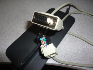
- DB9 to RJ45 hacked cable. Ideally should be DB9 to RJ12.
-
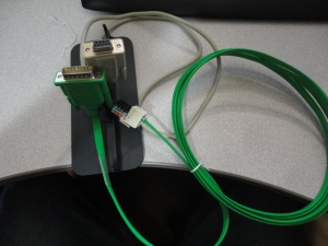
Here the EA-2CBL RJ12 plug is plugged into the center of the RJ45 jack.


( of course you can create your own DB9 to DB15 cable instead )

http://www.automationdirect.com/static/specs/cmorecables.pdf
DB9 |–| DB15
Pin 2 – Pin 3
Pin 3 – Pin 2
Pin 5 – Pin 5
Connecting the Arduino with the RS232 to TTL DTE board
Place jumpers on the RTS and CTS connections at the top of the board. 
Then make these following connections:
Arduino |—| DTE
5V – VCC
Gnd – GND
Digital pin 0 – RX (Use a jumper wire or place a switch in the middle of this connection.)
Digital pin 1 – TX
Do not connect the RTS or CTS pins from the board to anything.
Configure the Software.
For the Arduino:
Place the MOBUS library into the Arduino IDE library. See this for more information on how to do that: http://arduino.cc/en/Guide/Libraries
You can also copy the MODBUSslave example into the example folder.
Launch the Arduino IDE.
Open the MODBUSslave example. ( from the example menu or by navigating to it in the MODBUS library folder.
Now connect to your board. Remove the jumper to the RX pin. ( or turn off the switch if you used one) This will allow the computer to communicate with the Arduino. If you forget to do this, the DTE board will interfere with the upload of the sketch.
Upload the Example to the board.
Once complete, reconnect RX to D0.
C-more setup.
In the C-more software, Start a new project for the panel you have.
Go to Setup -> Panel Manager
On the com port, select the DEV001. Now would be a good time to rename this to ARDUINO.
Set PLC Protocol to Modicon Modbus RTU
Select direct connection
Set PLC SLAVE number to 1.
Baud Rate 9600
Parity None
Stop bit 1
Control RTS No
Require CTS No
Select RS 485 No
Byte Order High Byte, Low Byte
Word Order Low Word, High Word
Character Order in register Char1, Char2
Registers per Message 32
Coils per message 64
Register Write Function Code 06
Coil Write Function Code 05
Time out 30
Poll time 3
Click ok.
Let’s place a Numeric Display on the screen,
In the Data Display tag open the tag database to create a new tag.
Click on Add

Select ARDUINO for the device name, Give the tag a name like ReadOnlyRandom.
Set it to Unsigned INT 16
Select memory type 3
Enter an address of 1
Click ADD, Select the new tag Click OK. (notice that the PLC address is shown as 30001)
Click OK again to assign the tag to the display.
Save and send the project to the C-more.
Test it!
Connect the C-more to the Arduino using the com cable.
You should see LEDs on the DTE board flicker and a random number updating on the C-more screen. Congratulations, you have gotten past the biggest hurdle to getting a C-more to talk to an Arduino.
If you do not see this, check that you have RX and Digital pin 0 connected. Also try swapping the RX and TX connections.
Writing to an Arduino
Ok so now you can read from an Arduino, but how about writing to it.
Continuing with the example, let’s add a Numeric Entry in the same fashion as we did with the Numeric Display.
But this time when you add the new tag, Name it WriteableNumber with a memory type of 4 and an address of 9.

Save and transfer the project to the screen.
You should now see a 9 in the new entry.
Change the 9 to a different number. Now you have written to the Arduino.
To make use the register in the Arduino, update the example to use regBank.get(40009).
So in this post I covered how to setup the hardware to between a C-more touch screen HMI, and an Arduino. I also showed how to load the MODBUS library and example onto the Arduino. Lastly I showed how to configure the settings on the C-more to make use of the MODBUS RTU protocol in conjunction with the supported features of the Arduino.
The MODBUS library I used is not the only one available on the web, but it is the first one I got to work with a C-more.
Remember, when you are uploading to the Arduino, you must remove the RX connection.
In the next post, I will share a derived library that takes advantage of SoftSerial. This will allow You to connect the DTE board to Pins 2 and 3 instead of 0 and 1. There by allowing you to upload to the Arduino while remaining connected to the C-more.
Lastly I will share some methods to make it easy to read and write discrete bits using whole registers, instead of coils.
Please let me know what you think of this post. I welcome questions and feedback.
Resources:
http://code.google.com/p/arduino-modbus-slave/downloads/detail?name=MODBUS.zip&can=2&q=
http://www.nkcelectronics.com/RS232-to-TTL-converter-board-DTE-with-Male-DB9-33V-to-5V_p_369.html
http://en.wikipedia.org/wiki/Modbus
http://www.automationdirect.com/static/specs/cmorecables.pdf
http://media.nkcelectronics.com/downloads/rs232ttl_DTE_v1.1.pdf
http://forum.automationdirect.com
Windows Embedded Compact 7 updated to 2816
Leave a Comment
Windows Embedded Compact 7 has been updated with build 2816. This is the 13th update released. This update includes a major upgrade to Windows Embedded Silverlight Tools.
You can update Windows Embedded Silverlight Tools independent of Windows Embedded Compact 7, but it is generally recommended to allow Windows Embedded Compact 7 handle the upgrade for you. Simply let WEDU notify of you of the update, or launch the WindowsEmbeddedCompact7.exe installer from Add / Remove programs and select update.
Some XP users might have an issue with Install Level 9.
Leave a Comment
XP users may encounter an error while installing updates at Install level 9 (Update 8). The issue is resolved by updating to Install level 10 (Update 9). This update was released with the March build 7.0.2812.

Tags: Error Patch
